CREO Course by ANH
See Page Topics
Overview
Creo is a family or suite of design Software developed by Parametric Technology Corporation (PTC) in year 2011.
Creo is a Computer Aided Design tool used to create, analyze, view, and share designs downstream using 2D CAD, 3D CAD, parametric and direct modeling capabilities. Using Creo one can perform 3D Design, Industrial Design, Concept Design, Routed Systems Design, and Simulation.
Applications
Creo is used widely across Aerospace, Automotive, Alternative Energy, Construction, Consumer Product, Engineering services, Industrial Machinery & Heavy Equipment, Manufacturing, Mold Tool & Die, Oil & Gas, Packaging Industries, Process & Plants, and Education.
Course Highlights
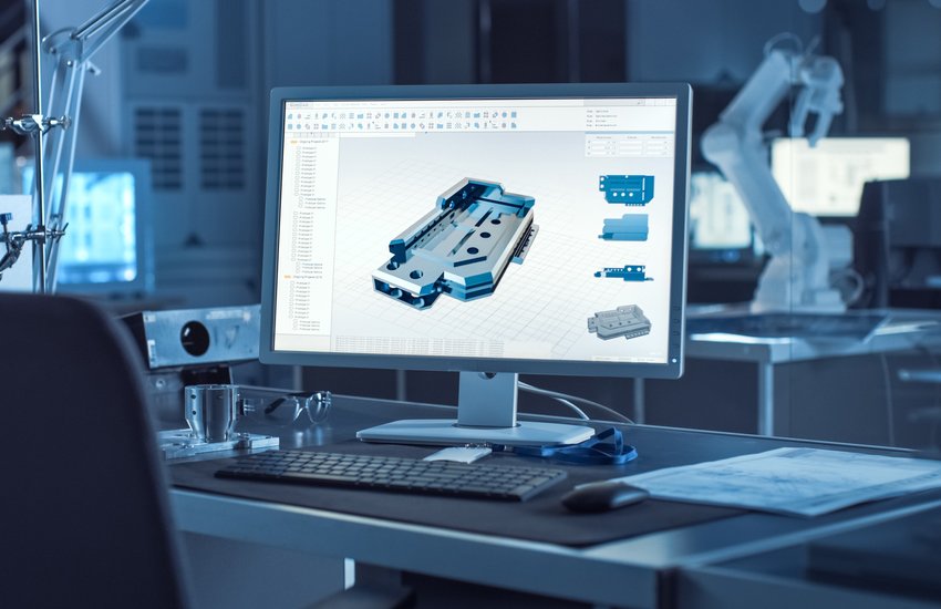
Why ANH‘s CREO Course?
What Sets Us Apart
– Industry expertise:AutoCAD course
Our trainers are experienced engineers with years of industry experience, ensuring you learn from those who have been in your shoes.
– Practical focus:AutoCAD course
Our training is focused on practical applications, not just theory, so you can apply your skills immediately.
– Access to latest technology:AutoCAD course
As an industrial engineering services company, we have access to the latest software and technology, which we incorporate into our training.
– Real-world projects:AutoCAD course
You’ll work on real-world projects, not just simulations, to gain valuable experience and build a portfolio of work.
– Mentorship:AutoCAD course
Our trainers will guide and mentor you throughout the course, providing feedback and support to help you improve.
Creo course: Foundation
Part Modeling
Advanced Part Modeling
Assembly Design
Advanced Assembly Design
Flexible Modeling
Sheetmetal Design
Drawing
Creo course: Advanced
Creo Advance- CAD Module
Creo-Analyst – CAE Module
Creo production- CAM Module
Duration
45 Hours Theory
45 Hours Practical
20 Hours Project work
Duration
30 Hours Theory
30 Hours Practical
20 Hours Project work
Technical Features
Creates Precise and Accurate 3D Complex Geometry based on the 2D Sketches
Parametric and Parent-Child Relation allows designers to modify design at any time
Feature based Modeling Software
Import and Export CAD Models for other CAD Tools
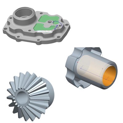
Creates 3D Models based on the Multiple Geometry
Capture the Details of the Model like Mass Properties
Manages the Cross- Section, Orientation an Representation of Models
Dynamically Editing of the Geometry
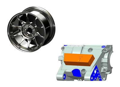
Smarter and Faster Assembly Modeling
Performance
Create Simplified representation on-the-fly
Leverage the real-time Interference detection
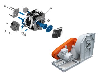
Top Down Design Approach
Use Fit, Form and Function Approach to Create Assembly Quickly and Accurately
Plan and Manage Large Assembly
Make Changes with confidence, knowing that modifications are automatically propagate from the design to manufacturing information
Quickly and efficiently customize product variants according to a customer’s unique requirements
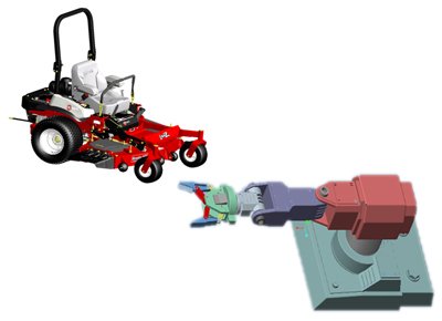
Accelerate Detailed Design by Editing Parametric Design faster and Easier
Easy Selection of Geometry, Including Surfaces and Shapes
Simultaneously changes multiple Entities
Work Faster with imported data like neutral file as IGES, STEP & CAD Software like SolidWorks, Inventor etc.
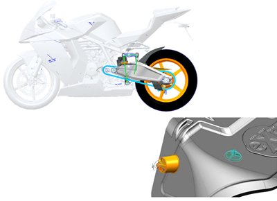
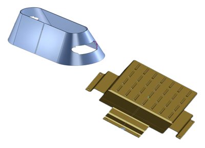
Create Sheetmetal Components faster and efficiently
Automatically Generates flat patterns from 3D Geometry
Use Varieties of Bend Allowance Calculations to Create Flat pattern of the designs
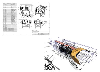
Create 2D and 3D Drawings according to International standards, including ASME, ISO and JIS Standard
Create an Associative Bill of material and Associate Balloon Notes Automatically
Automate the Creation of Drawings with Templates
Easy to Convert Drawings in PDF, Drawings and 3D PDF Formats
Design Precise curves and surfaces to achieve highly-engineering manufacturable products
Confidentially explore design variants by making fully associative changes at any time
Intuitive user interface provides direct surface editing capabilities, real-time feedback and allows rapid and extreme product design.
Create products that look better, sell better and get to the market faster
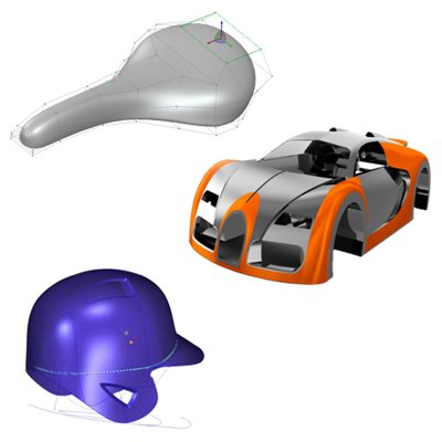
High-Quality, Parameterized surfaces can be immediately reused in a 3D detailed design process
Multilevel sub divisional modeling for more control over the surface, enabling finer detailing without altering the existing shape.
Build free form geometry at any point in the design, using as many as or as few constraints as desire For maximum design flexibility.
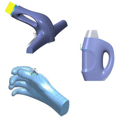
Easy to learn and use, Intuitive and direct modeling approach allows new or infrequent users to get up to speed quickly and create and edit 3D
Designs
Faster and More flexible part modeling and assembly modeling increases individual efficiency and Productivity.
Easily Accommodate late- Stage Changes to your engineering design faster and with less frustration with this fast and easy approach
Work More efficiently in multi CAD environment by easily incorporating and editing data from other CAD system.
Increase process efficiency
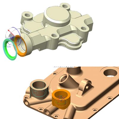
UI is based on weld symbols and terminology
Libraries for weld process and rod material
Extract valuable information from the model, such as mass properties, clearances, interferences, and cost data.
Determine amount of rod material required
Document welds using Industry standard Symbols
Define Joining requirements
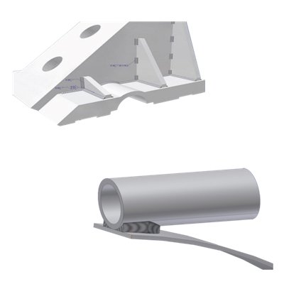
Ability to convert between assembly constraints and mechanism joints automatically
Easily control positions, speeds and accelerations of components and subassemblies
Create space claims provide collision warning
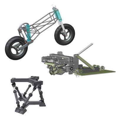
Simply reuse your model with options to include mechanism simulations
Visualize assembly/ disassembly sequences
Any and all design changes are immediately shown
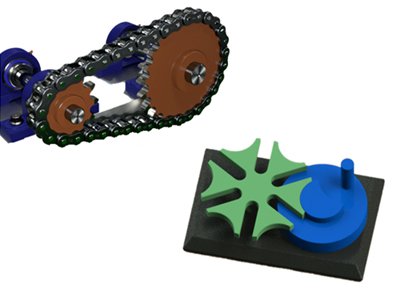
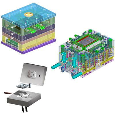
Automated functions and special GUI’s for 17 moldbase and component suppliers
Includes screws, ejector pins, sliders, lifters, cooling fittings, etc
Mold opening with interference checking of moldbase and components
All necessary clearance holes, threads, counter bores, etc. are automatically added to plates
Custom Components can be created, saved and reused
Standard and nonstandard mold components are marked
Ability to take your customer parts through the complete process
Supplier catalogs include : DME, DMS, EOC, FUTABA (Misumi) HASCO, KLA, MEUSBURGER, PEDROTTI, RABOURDIN, STRACK, PROGRESSIVE, NATIONAL,PCS,LKM
and others
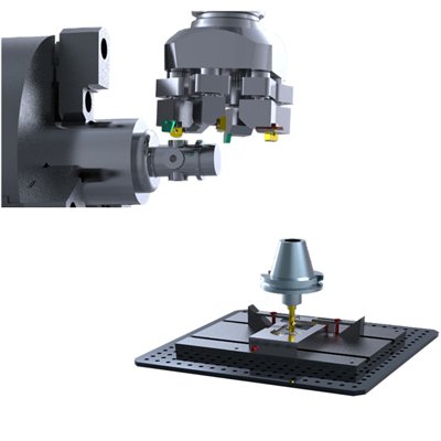
Multi-surface 3-aixs milling with support for high –speed machining 4-axis and 5-axis positioning NC-program creation, process documentation, post-processing and tool path verification/simulation Improves
product quality and Mfg consistency by generating tool paths directly on solid models Part of an integral CAD/CAM solution – no data translation required Reduces time –to market via associative tool path
updates to design changes
CREO Production Machining Extension
Includes all the capabilities of Creo Prismatic and Multi-Surface milling Extension Supports CNC Mills, 2 –axis and 4- axis CNC lathes, and 2 –axis and 4 – axis CNC wire EDM machines Provides low –level NC
sequence editing allowing precise toolpath control and optimization
Case Studies
Coming Soon
Let’s start working together! Get in touch with us!
If you would like to work with us or just want to get in touch, we’d love to hear from you!
